In mechanical engineering drawings, linear dimensions are classified in size, distances and radii (iso/tr 14638). The main features of leader lines. Web extension lines begin 1.5 mm from the object and extend 3 mm from the last dimension line. Basic conventions and applications for leader lines and reference lines — part 23: Dimensions make use of dimension lines, extension lines and leader lines.
However, extension lines can cross other extension lines or visible lines. The leader line can be a straight line or curved. Here is the list of cases where the continuous thin line will be used: A leader is a thin line used to connect a dimension with a particular area (figure 24). To ensure clear and consistent communication, drawings must adhere to.
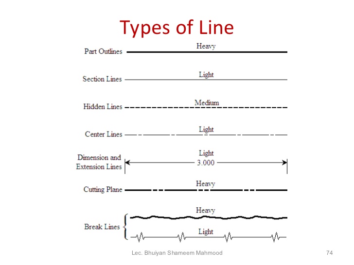
Limits of size — the largest acceptable size and the minimum acceptable size of a feature. They typically originate from a note, label, or callout and connect to the object or area being referenced. This type is also used to draw outlines of adjacent and revolved. Web standard engineering drawing line types. Web dimension, projection, leader, hatching lines.
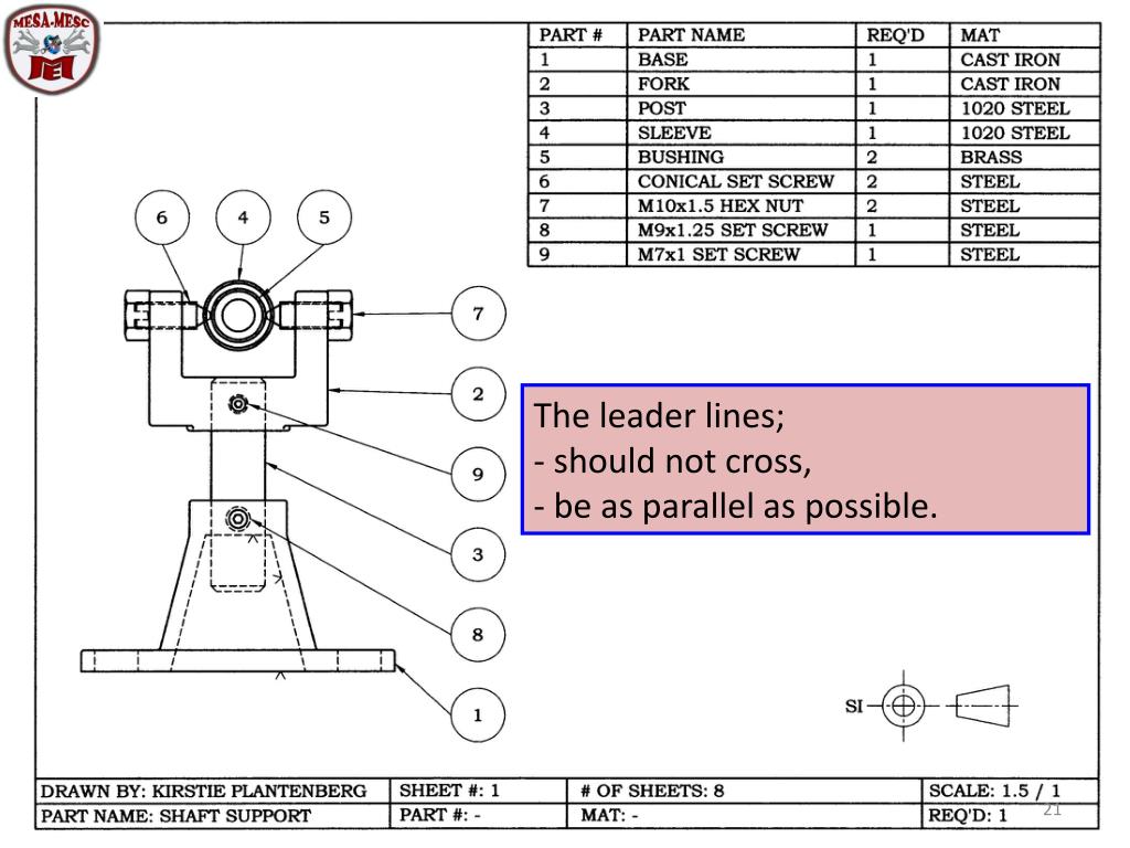
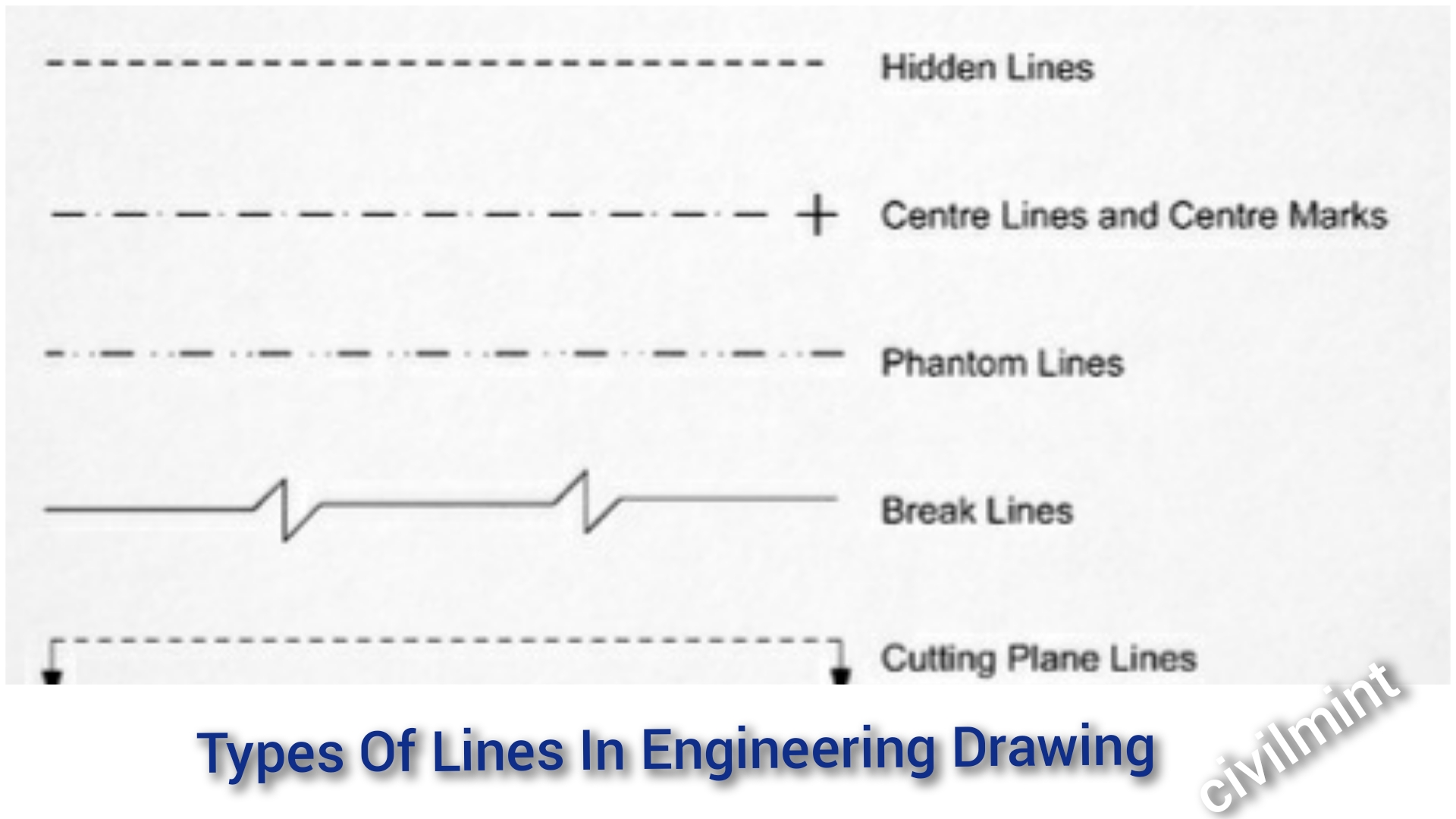
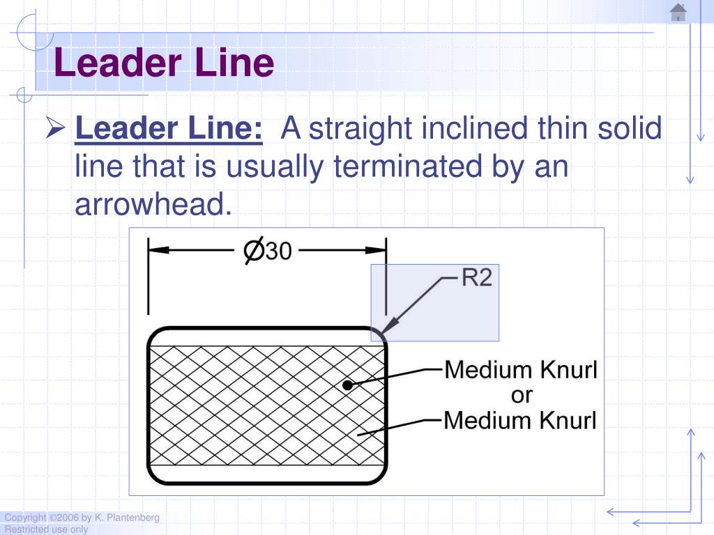
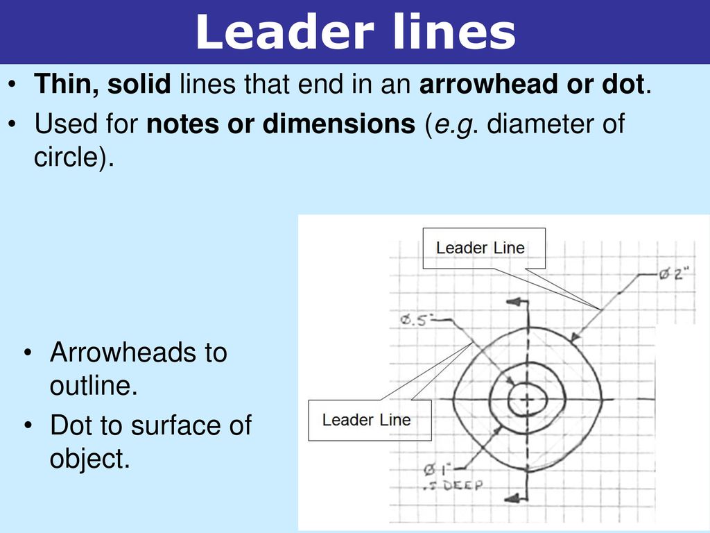
A leader may also be used to indicate a note or comment about a specific area. In these examples, the leader lines are indicated with a red arrow. Web note 1 to entry: Dimension, projection, leader, hatching type lines must be drawn thin and continuous. Lines on mechanical engineering drawings Web a leader line is a line that establishes a connection between a graphical representation of an item and some text. Types of lines include the following: Web engineering drawings are a critical part of the design and manufacturing process, providing detailed information on dimensions, materials, and tolerances. This statement is particularly true in regards to technical drawings. Web leader lines are used to direct attention to specific areas or features on an engineering drawing. To ensure clear and consistent communication, drawings must adhere to. In mechanical engineering drawings, linear dimensions are classified in size, distances and radii (iso/tr 14638). A leader is a thin line used to connect a dimension with a particular area (figure 24). Web leaders are lines in engineering drawings that provide a clear visual reference to other elements in the drawing. They are typically utilized when pointing to notes, labels, or callouts that provide additional information about a particular object or detail.
Leader Lines Represent Dimension Values In Drawings.
Extension lines and centerlines should not connect between views. To ensure clear and consistent communication, drawings must adhere to. Web leaders are lines in engineering drawings that provide a clear visual reference to other elements in the drawing. Limits of size — the largest acceptable size and the minimum acceptable size of a feature.
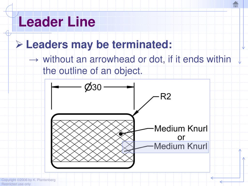
Leader Lines Are Straight Or Curved Lines That Have An Arrow Or Dot At One End And Are Used To Point To Specific Features Or Annotations In A Drawing.
A variety of line styles graphically represent physical objects. Web leader lines are used to direct attention to specific areas or features on an engineering drawing. A leader is a thin line used to connect a dimension with a particular area (figure 24). Web dimension, projection, leader, hatching lines.
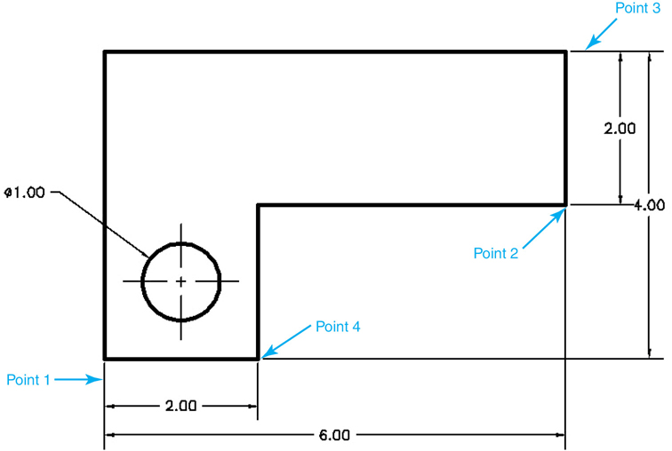
Leaders Are Used To Indicate Information About Hole Diameters, Radii, And Other Information That Occurs As A Specific Location Or On A Particular Surface On The Drawing.
They are used to connect parts or symbols, to indicate distances and dimensions, or to draw attention to an item in the drawing. The leader line can be a straight line or curved. They typically have an arrow or dot at one end and point to the object of interest. Types of lines include the following:
Web Dimension Lines Should Not Cross Extension Lines Or Other Dimension Lines.
Lines on construction drawings — part 24: All three line types are drawn continuous and thin. They are added using thin lines. There are several acceptable types of.
