Web of an engineering drawing. So once a manufacturing engineer gets the drawing, he can start the production process without a. Eo 1.4 statethe purpose of the notes andlegendsection of an engineering drawing. It is essential that this standard be used in close conjunction with asme y14.24, asme y14.34m, and asme y14.35m. It describes typical applications and minimum content requirements.
Improved placement of views on types of drawings samples to prevent unnecessary rework of drawings at a later date. Web drawing sheet s5 of our sample engineering drawings provides the exact way we expect the edge beams, internal strip footings and slab thickening to be constructed. In general, it provides necessary information about the shape, size, surface quality, material, manufacturing process, etc., of the object. An engineering drawing is a technical drawing that conveys any information required to manufacture a part that meets a customer’s specific needs. This standard establishes the essential requirements and reference documents applicable to the preparation and revision of engineering drawings and associated lists.
Web what is an engineering drawing? A study on information extraction method of engineering drawing tables | in getting an existing engineering drawing. However, if the object in figure 2 had a hole on the back. Web this article will tell you everything you need to know to create a clear, concise, and effective engineering drawing. The inside border encloses the.
The primary problem faced in learning and teaching of engineering drawing is the limited availability of text books that focus on the basic rules and specifications in relation to the drawing methods practiced in bangladesh. A complete understanding of the object should be possible from the drawing. Specifically, three different micro drawing processes were employed to form 50 micron ta1 pure titanium foils with varying grain sizes under different punch radii. The inside border encloses the. It is more than simply a drawing, it is a graphical language that communicates ideas and information. Engineering graphics is used in the design process for visualization,. Engineering graphics is an effective way of communicating technical ideas and it is an essential tool in engineering design where most of the design process is graphically based. The terms used in the table are clarified here: Web first, we will consider the sheet sizes, drawing format, title blocks, and other parameters of the drawing form. Drawings for specialized engineering disciplines (e.g., marine, civil, construction, optics, etc.) are not included in this standard. Whether you're a student embarking on an engineering career, a hobbyist looking to hone your. Sheet s5 also shows the footing specification at the timber post, the special requirements for slab step downs at wet areas, how the concrete masonry corners are to be reinforced. Improved placement of views on types of drawings samples to prevent unnecessary rework of drawings at a later date. Eo 1.2 state how the grid system on an engineering drawing is used to locate a piece of equipment. However, if the object in figure 2 had a hole on the back.
An Engineering Drawing Is A Technical Drawing That Conveys Any Information Required To Manufacture A Part That Meets A Customer’s Specific Needs.
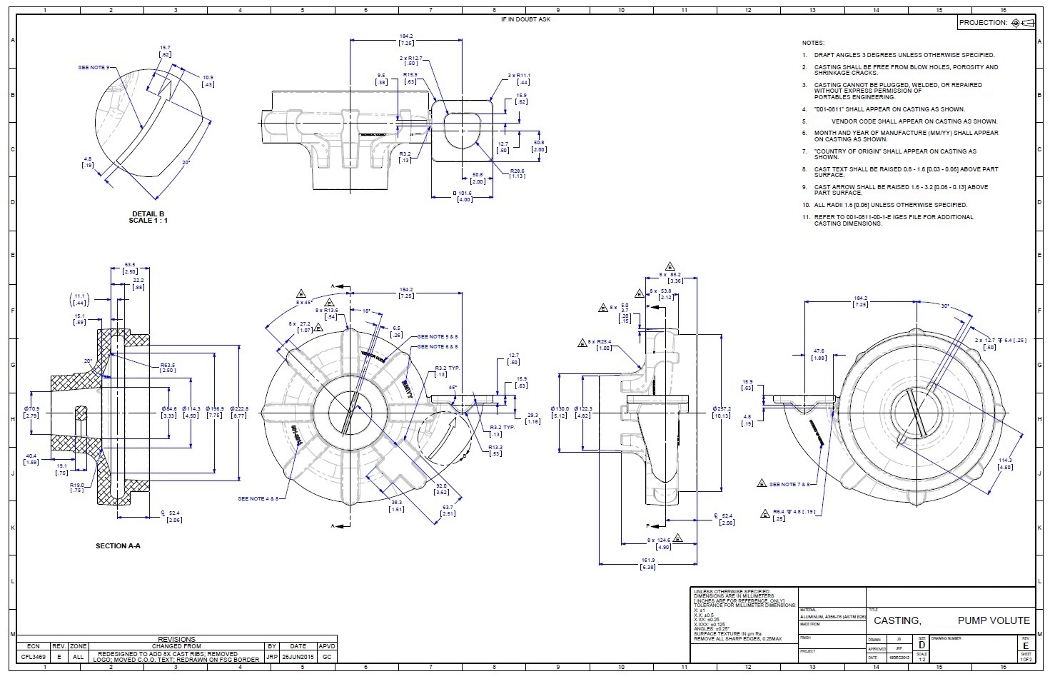
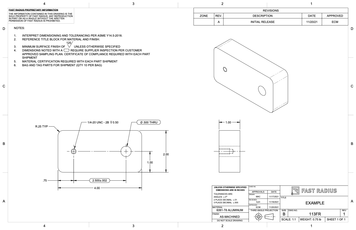
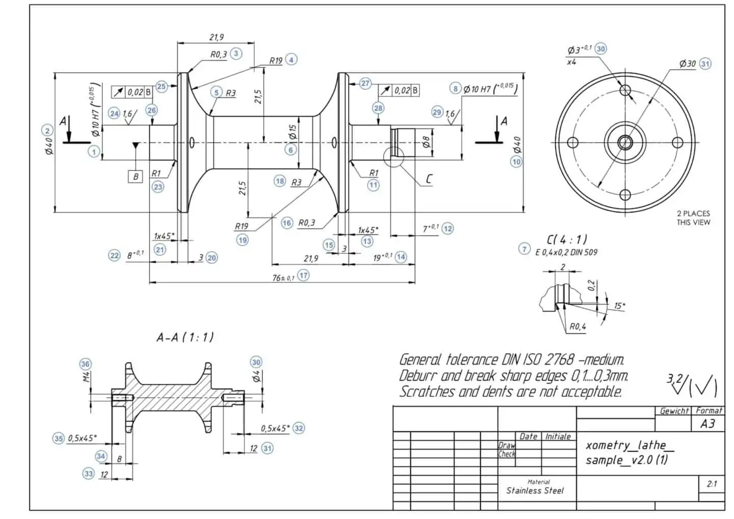
This standard establishes the essential requirements and reference documents applicable to the preparation and revision of engineering drawings and associated lists. In general, it provides necessary information about the shape, size, surface quality, material, manufacturing process, etc., of the object. Working drawings rely on orthographic projection and many other graphical techniques (sectioning, dimensioning, tolerancing, etc.) to communicate design information for production. An engineering drawing is a subcategory of technical drawings that show the shape, structure, dimensions, tolerances, accuracy and other requirements needed to manufacture a product or part.
Web Engineering Drawing Has Its Origin Sometime In 500 Bce In The Regime Of King Pharos Of Egypt When Symbols Were Used To Convey The Ideas Among People.
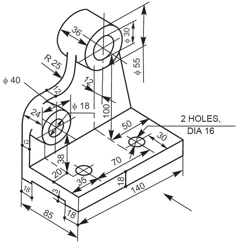
Web drawing sheet s5 of our sample engineering drawings provides the exact way we expect the edge beams, internal strip footings and slab thickening to be constructed. The terms used in the table are clarified here: If the isometric drawing can show all details and all dimensions on one drawing, it is ideal. It is essential that this standard be used in close conjunction with asme y14.24, asme y14.34m, and asme y14.35m.
So Once A Manufacturing Engineer Gets The Drawing, He Can Start The Production Process Without A.
One can pack a great deal of information into an isometric drawing. Continuing its reputation as a trusted reference, this edition is updated to convey recent standards for Web engineering drawings (aka blueprints, prints, drawings, mechanical drawings) are a rich and specific outline that shows all the information and requirements needed to manufacture an item or product. Drawings for specialized engineering disciplines (e.g., marine, civil, construction, optics, etc.) are not included in this standard.
Standard Sheet Sizes In Table 1 Are Shown The Most Widely Used A And B Series Of The Iso Drawing Sheet Sizes, With A4 Being The Most Popular Size.
Web this article will tell you everything you need to know to create a clear, concise, and effective engineering drawing. Through standardized language and symbols,. However, if the object in figure 2 had a hole on the back. A study on information extraction method of engineering drawing tables | in getting an existing engineering drawing.


